|

|

|

|
TCIM: testing 9.38 MHz clock
This document is based on work done with Allan Hansen 10-Oct-2000.
One problem with the TCIM is that the 9.38 clock (beam clock) has an unequal duty factor when it gets to the VME backplane. It is high more that it is low. Here are a series of plots showing the beam clock signal from the place it enters the board until it reaches the backplane. It is a complicated path, as shown in the following sketch, which I extracted from the schematic:
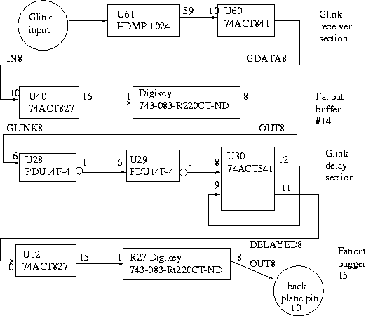
The following scope shots were taken at various places along the path of the beam clock signal in the TCIM. You can see that the signal slowly gets wider as it goes through the tcim. One horizontal arrow is 53 ns long and the other is 106 ns long.
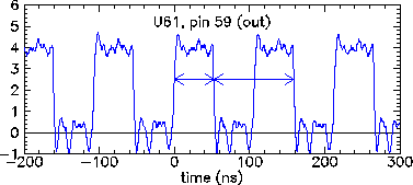
| At U61, pin 59, HDMP-1024 output, in G-link receiver block |
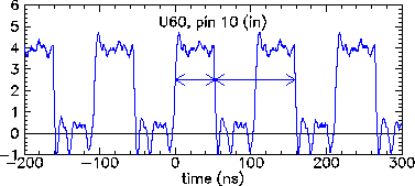
| At U60, pin 10, 74ACT841 input, in G-link receiver block |
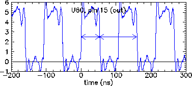
| At U60, pin 15, 74ACT841 output, in G-link receiver block |
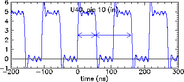
| At U40, pin 10, 74ACT827 input, in fanout buffer 14 block |
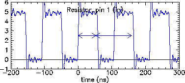
| At a Digikey 743-083-R220CT-ND resistor (R number unknown), pin 1, input, in fanout buffer 14 block |
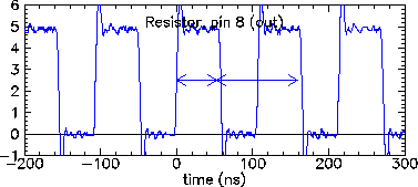
| At a Digikey 743-083-R220CT-ND resistor (R number unknown), pin 8, output, in fanout buffer 14 block |
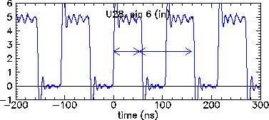
| At U28, pin 6, PDU14F-4 input, in G-link delay block |
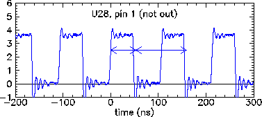
| At U28, pin 1, PDU14F-4 output-bar, in G-link delay block |
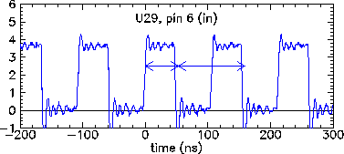
| At U29, pin 6, PDU14F-4 input, in G-link delay block |
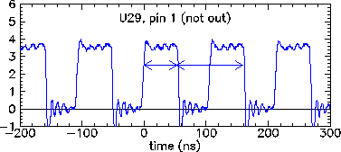
| At U29, pin 1, PDU14F-4 output-bar, in G-link delay block |
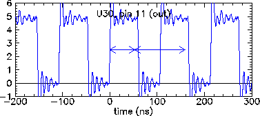
| At U30, pin 11, 74ACT541 output, in G-link delay block |
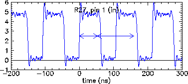
| At R27, pin 1, Digikey 743-083-RT220CT-ND input, in fanout buffer 15 block |
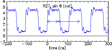
| At R27, pin 8, Digikey 743-083-RT220CT-ND output, in fanout buffer 15 block |