|

|

|

|

Looking at the ADC_CLK_EN pulse out of the AMU/ADC (in this case AMU/ADC 1 was tested) allows us to check whether these SLCT bits are working correctly. This is done by looking at the width of ADC_CLK_EN. As described in MVD note 97-47 (a.k.a. Phenix note 333) the width of ADC_CLK_EN

The variable n is
the number of desired bits, f is the ADC clock frequency, and
Toh is time needed for setup overhead. The variable
n is the number of bits used in the conversion and would be either 9,
10, 11, or 12. The exponent is n-
1, instead of n, because the counter circuit counts on both the
rising and falling clock edges and thereby reducing the time required by a
factor of 2. The tests shown below used a 40MHz clock (=4X clock), so we expect
9 bits gives a width of 6.4 microsec,
10 bits gives a width of 12.8 microsec,
11 bits gives a width of 25.6 microsec,
12 bits gives a width of 51.2 microsec.
There is one further complication, there is a timeout built into the
heap manager. If will only 200 beam clocks (beam clock is 10MHz) or 20
microsec. So, in 11 and 12 bit mode, the pcmcm will not reach full scale
on the ADCs.
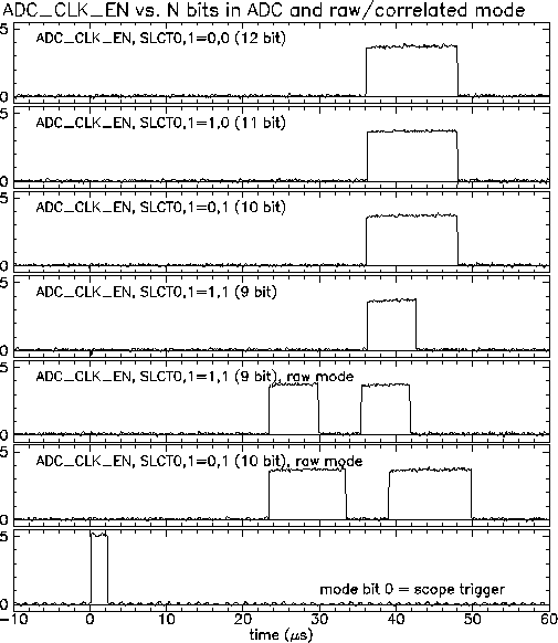
The first four plots below show ADC_CLK_EN for 12, 11, 10, 9 bit mode. The test used the "Bench calibration" mode. This should not affect the width of ADC_CLK_EN, but the scope is triggered on Mode bit 0, which initiates the bench calibration procedure. This trace is shown on Traces 5 and 6 show ADC_CLK_EN in the "raw mode" (pre and post samples digitized separately). Notice that the length of ADC_CLK_EN is too short for 10, 11, 12 bit digitization. It seems to be 12 microseconds wide. The system seems to time out at about 120 beam clocks (12 microsec), rather than 200 beam clocks (20 microsec) as it should. Why it does this is an unresolved problem. It times out at the correct (200) number of beam clocks when we use a slower clock. The picture below is also available as a postscript file.
