| ps version |
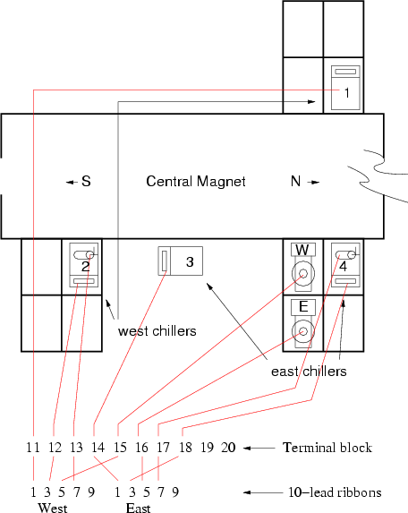
The chillers are (re)numbered so that 1-4 is South-North in the hall (see
below).

| ps version |
| contains | in/out | |
|---|---|---|
| box 1 |
filter fan pot for fan heat exch box H1 sensor T1F1 sensor level sensor drain valve drain relay |
3" air return 110V (fan, valve) 12V for motor 2" air hoses (2) antifreeze (4) H1 ribbon T1F1 ribbon L1 ribbon water drain |
| box 2 |
chiller 4(2) = E2(W2) chiller relay liquid throttle valve pump pump relay T17(14) sensor T18 sensor F9(4) sensor F10(5) sensor degassing can heat exchanger |
bldg water in/out antifreeze in/out chiller 208V chiller 5V control chiller RS232 110V pump 5V control T14(17) ribbon T(18) ribbon F4 ribbon F5 ribbon degassing exhaust FR75 in/out |
| box 3 |
chiller 3(1) = E1(W1) chiller relay T(11) sensor T(12) sensor T15(13) sensor T16 sensor |
bldg water in/out antifreeze in/out chiller 208V chiller 5V control chiller RS232 T(11) ribbon T(12) ribbon T15(13) ribbon T16 ribbon |
 ps
ps