Gluing Procedure for Si strip detector + katon cable assembly
to MCM + MCM output cable assembly
Toshiyuki Shiina
The University of Alabama in Huntsville
September 22, 1999
Updated Nov 17, 2000
Materials Needed
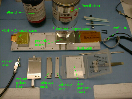
- Components
- MCM + MCM Output Cable Assembly
- Silicon Strip Detector + Kapton Cable Assembly
- Jig Parts
- Base Plate
- Correct Vacuum Pickup Fixture
- Adhesive Stop
- Correct Adhesive Mask
- Glass Alignment Fixture
- Adhesive
- Densil Adhesive
- Densil Primer IV
- Miscellaneous
- Ethyl Alcohol
- Lint-Free Swabs
- Latex Gloves
- Scalpel with Fresh Blade
- Plastic tipped tweezers
- Silicon Detector Protective Sleeve
- Wrist Strap (grounded)
- ESD safe rubber mat
Procedure
- Ensure that the ESD safe rubber mat on the fan bench and the wrist strap
are properly grounded to protect MCM's from ESD.
- Ensure the vacuum pump is turned on. If needed, turn on vacuum pump by plugging
it into outlet box on the floor next to the
lower left hand area of the fan bench.
- Turn on fan on fan bench (bottom right).
- Cover the silicon strip detector with a protective sleeve to avoid scratches on the detector.
- The gluing will occur on the narrower end of the kapton cable.
Using a lint-free swab and ethyl alcohol, clean both the top
and bottom of this end of the cable.
- Remove the Densil Primer IV from the chemical locker on top
of the fan bench. Gently swirl the can of primer to mix the contents. Open
the can carefully, away from you, in case pressure has built up in the can.
Dip a lint-free swab into the primer, and apply a thin layer of primer
the back side (ground plane side) of the kapton cable.
Allow this to dry completely; this should take around 2 minutes or less.
- Slip the primer fence (the bridge piece with the wire soldered to it) over
the bond-pad end of the MCM.
Dip a small lint-free swab into the Densil Primer, and apply a thin coat of primer
to the bonding pads of the MCM (256 traces), up to the wire of the primer
fence. Remove the primer fence. Place the MCM in the base plate. Allow the
primer to dry thoroughly (about 2 minutes or less). Return the primer to the
chemical locker on top of the fan bench.
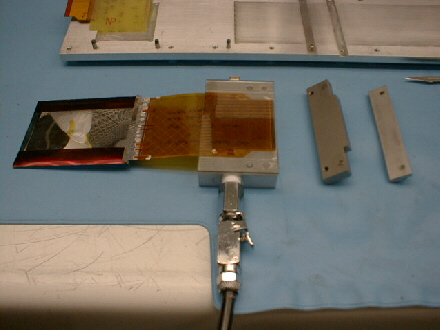
- Lay the cable on the screen side of the vacuum pickup fixture, in approximately the correct
position, i.e. ground plane up, centered on the screen, with the end flush with the edge of the
pickup fixture (on the side nearest the registration pin holes). Slide the vacuum pump hose
connector into the female receptable on the side of the vacuum pickup fixture, but don't complete
the connection yet.
- Lay the glass alignment fixture on top of the vacuum pickup fixture,
making sure the registration pins are in the correct holes on the pickup
fixture. The fixture has a little play: position is optimal when the fixture
is pushed into the cable direction. Align the cable with the glass alignment
fixture by moving the cable around until the ground grid on the alignment
fixture is perfectly aligned with the ground grid on the cable.
NOTE:
some patience is required to get this alignment just right. When the cable
is aligned perfectly, virtually none of the gold traces from the cable are
visible--only the darker traces on the pickup fixture can be seen. The gluer
must make sure that this alignment is good over the entire area of the glass
alignment fixture.
- When the cable is well aligned, slide the vacuum pump hose connector fully
into the female receptacle on the vacuum pickup fixture to engage the vacuum.
Ensure that this has not changed the alignment. Remove the glass fixture.
- Cut a small piece (roughly 1/2" by 3") of Densil adhesive from the roll
using a scalpel with a fresh blade.
- Lay the adhesive piece on the glass work surface, with the protective sheet
down. Using the edge of the adhesive cutting mask as a guide, cut a straight
edge to the adhesive using a sharp scalpel. Warning--if one is not careful
or uses a dull scalpel blade, it is very easy to crinkle up the adhesive,
which makes it unusable for our purposes.
Ensure the adhesive is not crinkled up.
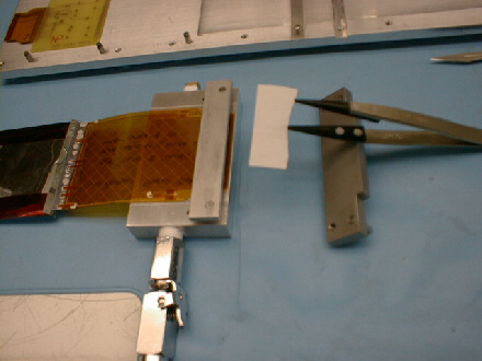
- Place the adhesive stop onto the pickup fixture, using the
registration pins. Using the tweezers, apply the adhesive to the cable, with
the protective sheet facing up and the adhesive side contacting the cable. Use
the adhesive stop to locate the straight edge you cut in the previous step.
When it is properly placed, run the rounded end of the tweezers over the
protective sheet to ensure good contact to the cable. Remove the adhesive stop
from the pickup fixture.
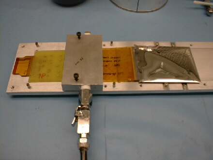
- Place the adhesive mask on the pickup fixture, using the registration pins.
With two 8-32 x 3/4" screws, tighten down the adhesive mask; this will allow for a pressure
cure of the adhesive-cable bond. Allow the adhesive to pressure cure for 1/2 hour.
- With the adhesive mask as a guide, trim away the excess adhesive
using a sharp scalpel. Sides first, face last. Remove the adhesive mask.
- Disconnect the vacuum, and using the special fine-tip cutters, trim about
0.5 mm off each end of the cable. Put the cable back onto the pickup fixture,
using the same procedure and care as in step 8.
- Place the adhesive stop back over the cable. Hold the stop down with
your finger; this will serve to help hold the cable in place as the gluer removes
the protective sheet from the adhesive. Using a scalpel, lift up one end of the protective sheet.
Note that it is easy to get only part of the protective sheet--be sure the adhesive
appears clear in the area where the sheet is lifted up. When an end of the protective
sheet is pulled up, grab it with the tweezers, and gently pull it the rest of the way off.
Remove the adhesive stop.
- Using the registration pins to align, place the pickup fixture and cable
on the glue jig base plate, wirebonding pads up. Note: Be very careful not to drop the silicon
detector.
This should allow the adhesive to
contact MCM. Using two 8-32 x 3/4" screws, tighten down the pickup fixture,
which will allow for a pressure cure of the adhesive. After the fixture is screwed down,
the vacuum can be disconnected. Allow the adhesive to pressure cure for a minimum of 2 hours.
- Package assembly for shipping to wirebonder.