Gluing Procedure for Si strip detector to kapton cable


Materials Needed

  1. Components
  2. Jig Parts
  3. Adhesive
  4. Miscellaneous


Procedure

  1. Ensure the vacuum pump is turned on. If needed, turn on vacuum pump by plugging it into outlet box on the floor next to the lower left hand area of the fan bench.

  2. Turn on fan on fan bench.

  3. The gluing will occur on the wider end of the kapton cable. Using a lint-free swab and ethyl alcohol, clean both the top and bottom of this end of the cable.

  4. Remove the Densil Primer IV from the chemical locker on top of the fan bench. Gently swirl the can of primer to mix the contents. Dip a lint-free swab into the primer, and apply a thin layer of primer to the back side (ground plane side) of the cable. Allow this to dry completely; this should take around 2 minutes or less.

  5. Lay the cable on the screen side of the vacuum pickup fixture, in approximately the correct position, i.e. ground plane up, centered on the screen, with the end flush with the edge of the pickup fixture (on the side nearest the registration pin holes). Slide the vacuum pump hose connector into the female receptacle on the side of the vacuum pickup fixture, but don't complete the connection yet.

  6. Lay the glass alignment fixture on top of the vacuum pickup fixture, making sure the registration pins are in the correct holes on the pickup fixture.

  7. Align the cable with the glass alignment fixture by moving the cable around until the ground grid on the alignment fixture is perfectly aligned with the ground grid on the cable. NOTE: some patience is required to get this alignment just right. When the cable is aligned perfectly, virtually none of the gold traces from the cable are visible--only the darker traces on the pickup fixture can be seen. The gluer must make sure that this alignment is good over the entire area of the glass alignment fixture.


  8. When the cable is well aligned, slide the vacuum pump hose connector fully into the female receptacle on the vacuum pickup fixture to engage the vacuum. Ensure that this has not changed the alignment.

  9. Cut a small piece (roughly 1/2" by 3") of Densil adhesive from the roll using a scalpel with a fresh blade.

  10. Lay the adhesive piece on the table, with the protective sheet against the table. Using the edge of the adhesive mask as a guide, cut a straight edge to the adhesive using a sharp scalpel. Warning--if one is not careful or uses a dull scalpel blade, it is very easy to crinkle up the adhesive, which makes it unusable for our purposes. Ensure the adhesive is not crinkled up.

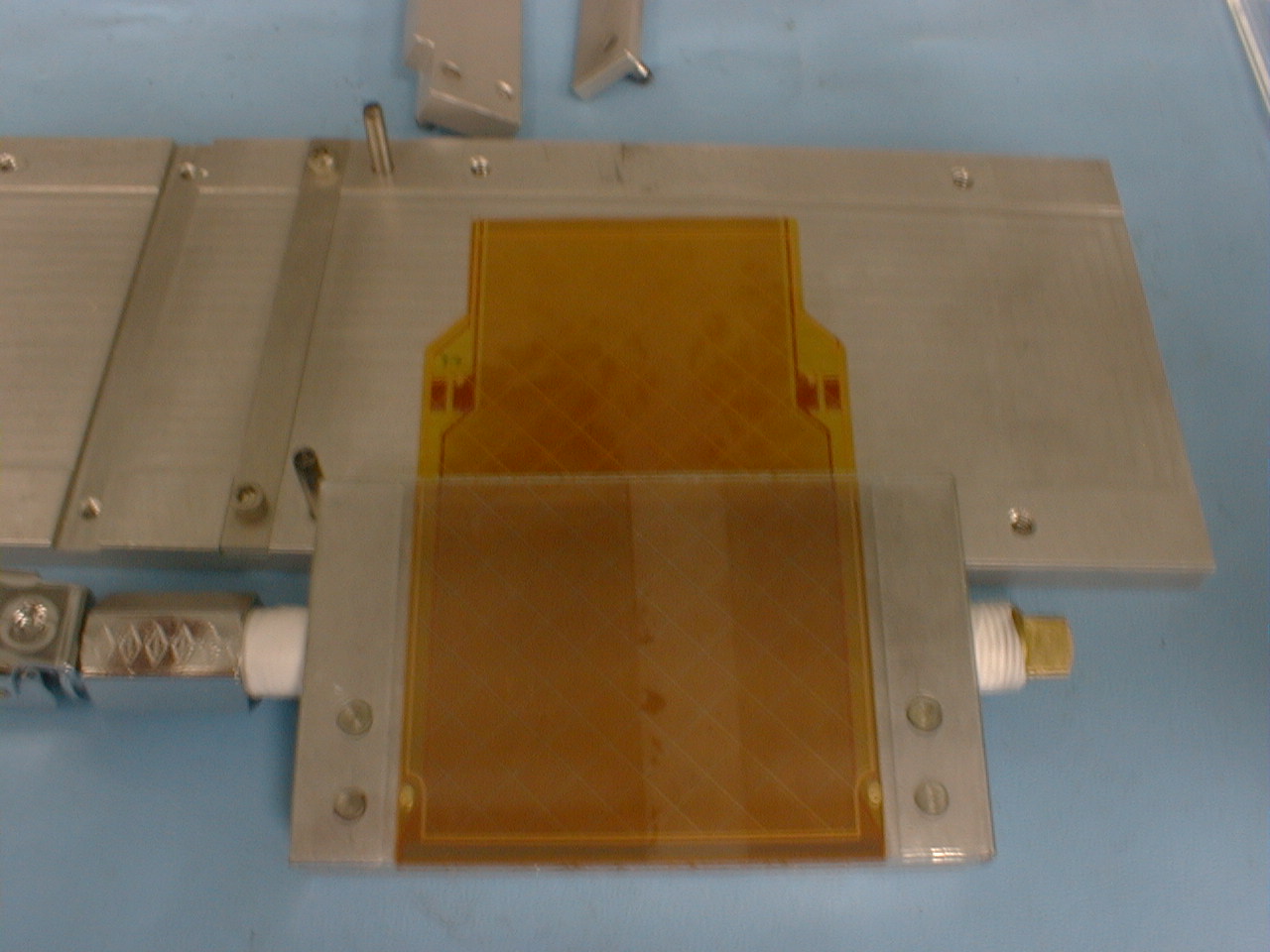
  11. Place the adhesive stop onto the pickup fixture, using the registration pins. Using the tweezers, apply the adhesive to the cable, with the protective sheet on the top and the adhesive side contacting the cable. Use the adhesive stop to locate the straight edge you cut in the previous step. When it is properly placed, run the rounded end of the tweezers over the protective sheet to ensure good contact to the cable. Remove the adhesive stop from the pickup fixture.


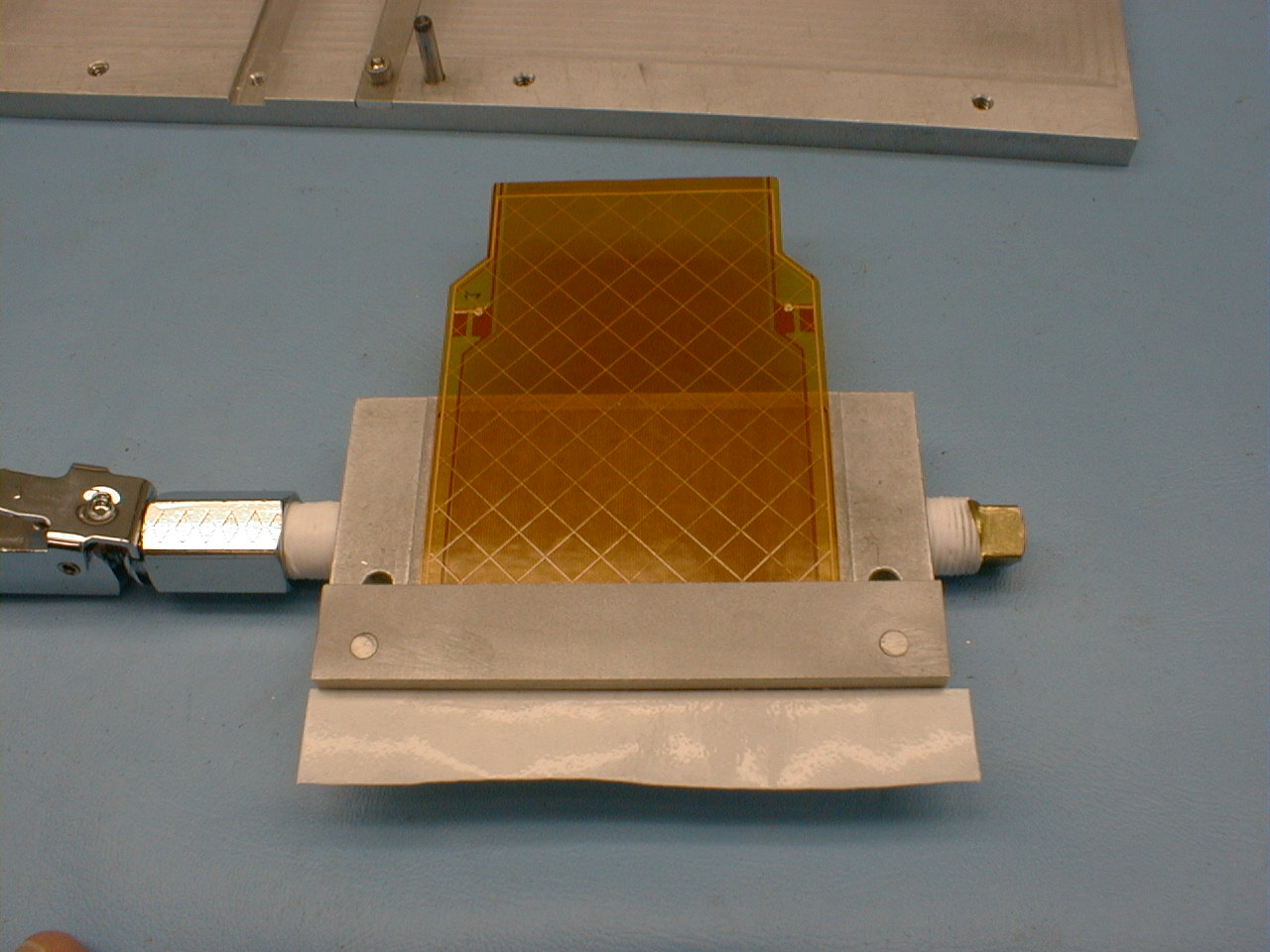
  12. Place the adhesive mask on the pickup fixture, using the registration pins. With two 8-32 x 3/4" screws, tighten down the adhesive mask; this will allow for a pressure cure of the adhesive-cable bond. Allow the adhesive to pressure cure for 1/2 hour.


  13. With the adhesive mask as a guide, trim away the excess adhesive using a sharp scalpel. Remove the adhesive mask.

  14. Using the glass alignment fixture, ensure that the alignment is still good, readjusting if necessary.

  15. Place the adhesive stop back over the cable. Hold the stop down with your finger; this will serve to help hold the cable in place as the gluer removes the protective sheet from the adhesive. Using a scalpel, lift up one end of the protective sheet. Note that it is easy to get only part of the protective sheet--be sure the adhesive appears clear in the area where the sheet is lifted up. When an end of the protective sheet is pulled up, grab it with the tweezers, and gently pull it the rest of the way off. Remove the adhesive stop.

  16. Using a lint-free swab and ethyl alcohol, clean the wirebond area of the silicon detector

  17. Dip a lint-free swab into the Densil Primer, and apply a thin coat of primer to the wirebond area of the silicon detector. Allow the primer to dry thoroughly (about 2 minutes or less). Return the primer to the chemical locker on top of the fan bench.

  18. Place the detector stop strip in the appropriate channel on the glue jig base plate and screw into place (the appropriate channel is determined by whether this is a short or long silicon detector). Place the detector in the cavity on the glue jig base plate.

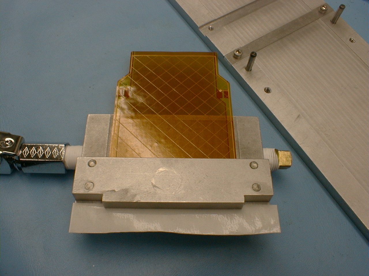
  19. Using the registration pins to align, place the pickup fixture and cable on the glue jig base plate, cable side down. This should allow the adhesive to contact the silicon detector. Using two 8-32 x 3/4" screws, tighten down the pickup fixture, which will allow for a pressure cure of the adhesive. After the fixture is screwed down, the vacuum can be disconnected. Allow the adhesive to pressure cure for a minimum of 2 hours.
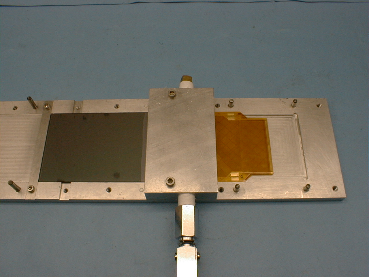

  20. Remove the pickup fixture from the glue jig base plate. Typically, the adhesive has been pressed out somewhat and the silicon/cable assembly is lightly attached to the glue jig base plate. To remove the assembly, slide the rubberized tip of tweezers under the silicon and toward the glue joint. The assembly should pop loose from the base plate.

  21. Package assembly for shipping to wirebonder.


Any questions should be addressed to Mike Bennett, mjbennett@lanl.gov, 505-665-2760