 |
schematic ps version |
 |
layout ps version |
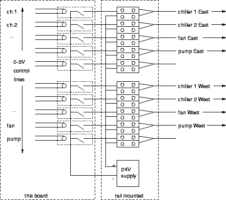
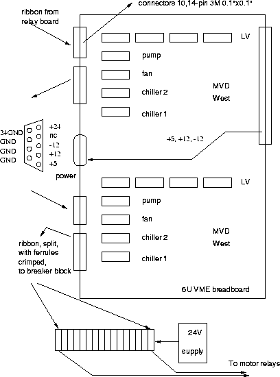
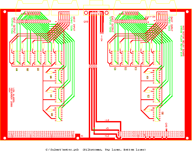
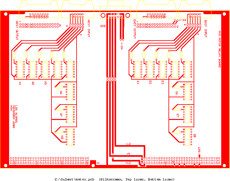
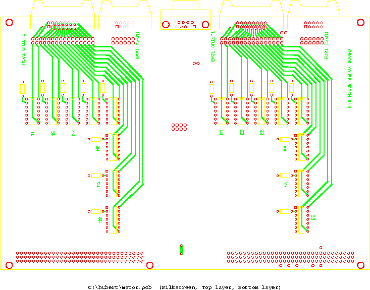
The motors are switched by mechanical relays which need 24V. This board sits between the 'relay board' and these mechanical relays. It is housed in the MVD ancillary VME crate, but does not use anything from the backplane. A ribbon with a 10-pin 0.1" connector comes from the relay board. The 0-5V signals on this input ribbon switch miniature relays on this board that send 24V to the motor relays, via a terminal block located on the rail just below the VME crates. The 24V is supplied locally by a supply located near the terminal block.
 |
schematic ps version |
 |
layout ps version |
| This is the PCB file: motor.pcb | |
 |
ps |
 |
ps |
 |
ps |
| function | input connector pin
even pins are GND | output connector pin |
|---|---|---|
| chiller 1 | 1 | 1,2 |
| chiller 2 | 3 | 3,4 |
| fan | 5 | 5,6 |
| pump | 7 | 7,8 |
| LV | 9 | 9,10 |
| 11,12 | ||
| 13,14 | ||
| 15,16 |