 postscript
This is the front viev of the MVD LV crate:
 postscript
 ps, Steve's pdf |  ps, pdf |  ps, pdf |
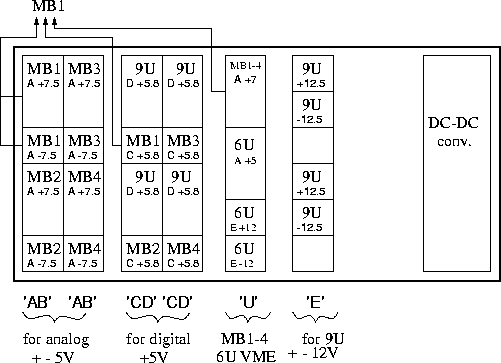
With this, the view from the back is as follows. In black the voltages.
The red numbers in parentheses refer to the 24V control lines.
On Steve's header board, where the ribbons come up from the LV crate to screw
terminals, there are blocks of connections corresponding to our 6 modules. For
each module, there are 6 possible enable lines (corresponding to max 6 bricks
per module), then 6 DC status return lines an 2 temperature monitoring points.
 lv_block.ps
| slot | function | name | ganged | switch | Adam bit |
|---|---|---|---|---|---|
| 1 (AB) | MB1 +-5 analog | ENC1 | MVD East | (1) | 0 |
| MB2 +-5 analog | ENC4 | MVD West | (2) | 1 | |
| 2 (AB) | MB3 +-5 analog | ENC1 | MVD East | (3) | 2 |
| MB4 +-5 analog | ENC4 | MVD West | (4) | 3 | |
| 3 (CD) | 9U +5 | ENC1 | - | (5) | 4 |
| MB1 +5 digital | ENC3 | MVD East | (6) | 5 | |
| MB2 +5 digital | ENC6 | MVD West | (7) | 6 | |
| 4 (CD) | 9U +5 | ENC1 | - | (8) | 7 |
| MB3 +5 digital | ENC3 | MVD East | (9) | 8 | |
| MB4 +5 digital | ENC6 | MVD West | (10) | 9 | |
| 5 (U) | MB1->4 +5 | ENC1 | - | (11) | 10 |
| 6U +5 | ENC3 | - | (12) | 11 | |
| 6U +-12 | ENC5 | - | (12) | 12 | |
| 6 (E) | TIM +-12 | ENC1 | - | - | 13 |
| TIM +-12 | ENC4 | - | - | (13) |
| Here is how the power to the mother boards is hooked up.
To make it less confusing, it is shown separately for each of the MB's: | |
 ps |  ps |
 ps |  ps |