Hardware
back to 'LANL LHCb home'
| ||||||
Running log in inverse chronological order: | ||||||
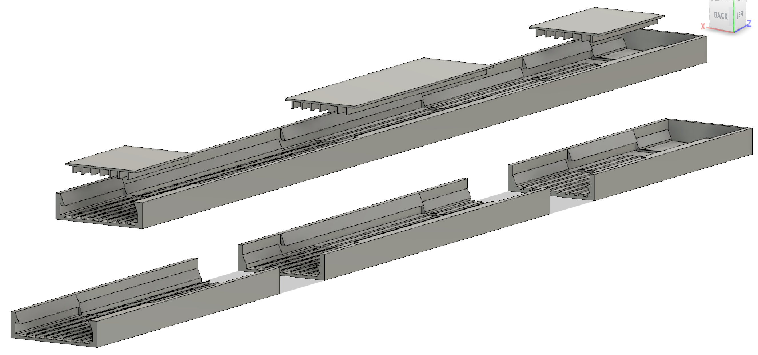
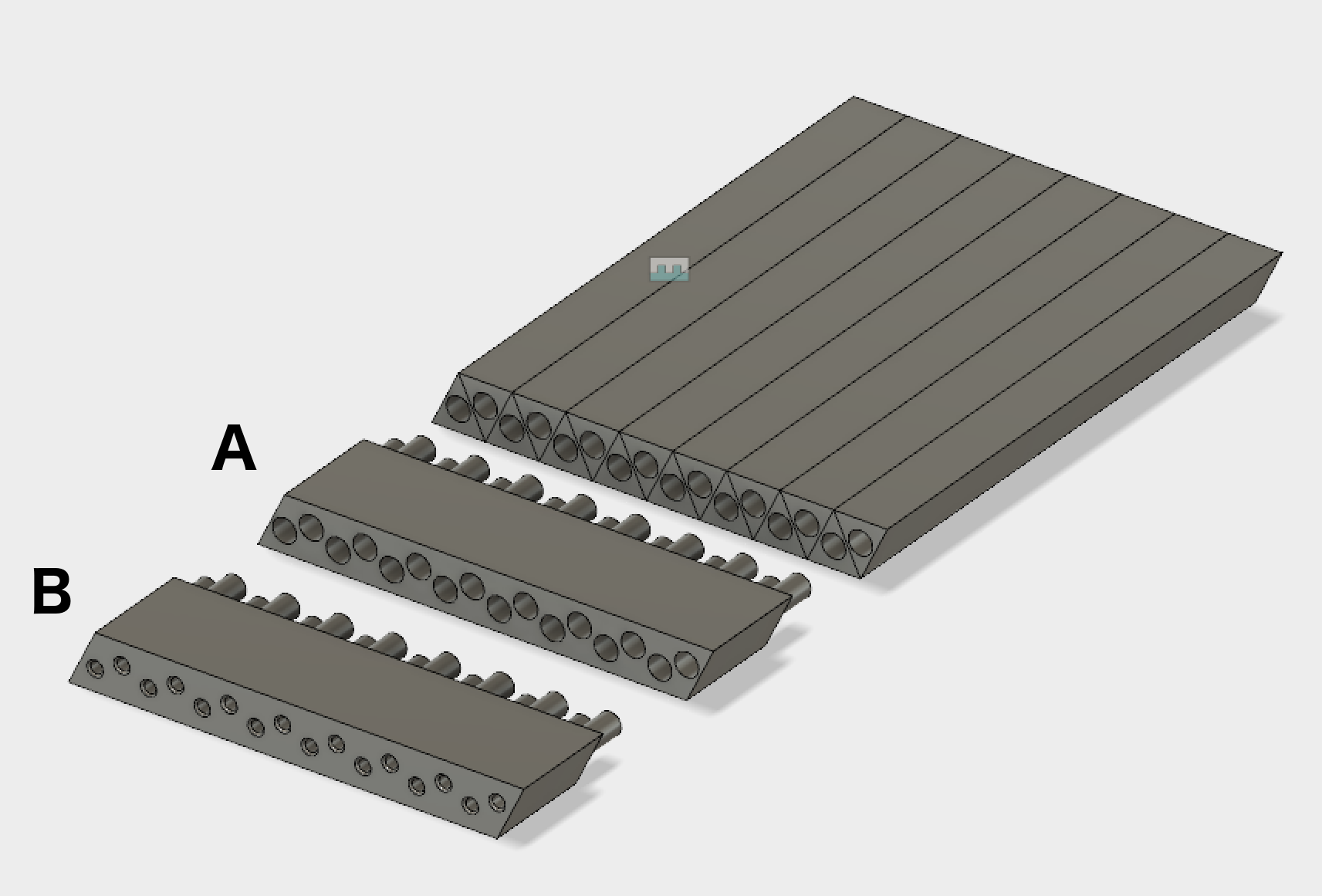
| (36) I 3D printer a 50cm tray to assemble a detector section, and did a test assembly. Details for the 16-bar prototype: assembly tray (1). Details for the 50-cm prototype: assembly tray (2). more on the 50-cm prototype: assembly tray (3). more on the 50-cm prototype: prototype (4). ←current work
more on the 1-meter+ panels
panels (5).
| 
| |||||
| (35)
Berenice Garcia drew up the new configuration. This no longer has Y-U-V planes, but segmentation in Y to take care of higher occupancy near the midplane.
| 
| |||||
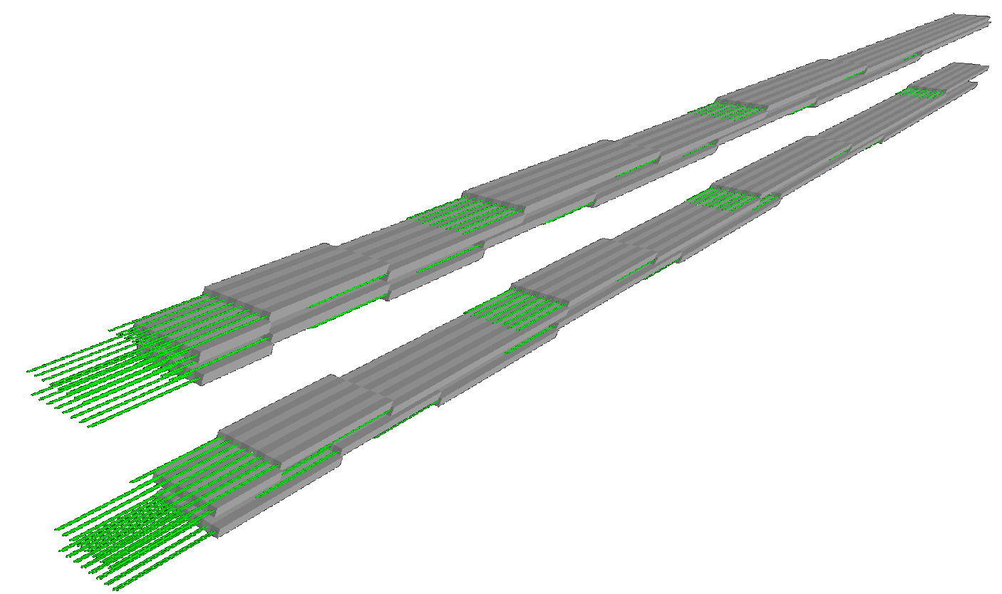
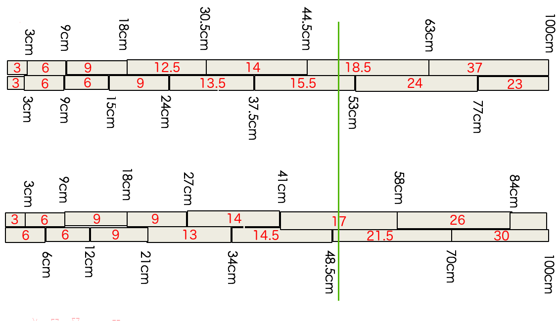
Note that for each of the 4 layers, there are 6 sets of fibers that have to be routed to the end on the right. | 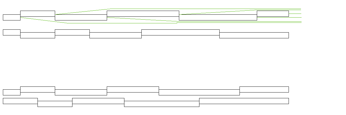
| |||||
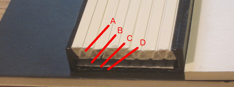
These are the bars of the top layer (3, 6, 9, 12.5 ,14, 5.5cm). We need a tray to hold them during assembly.
The tray has to have raised supports for groups B, D,
F.
After this, bars F are placed, followed by
D and B. Fibers from the last two groups pass over the top of D and
F.
| 
| |||||
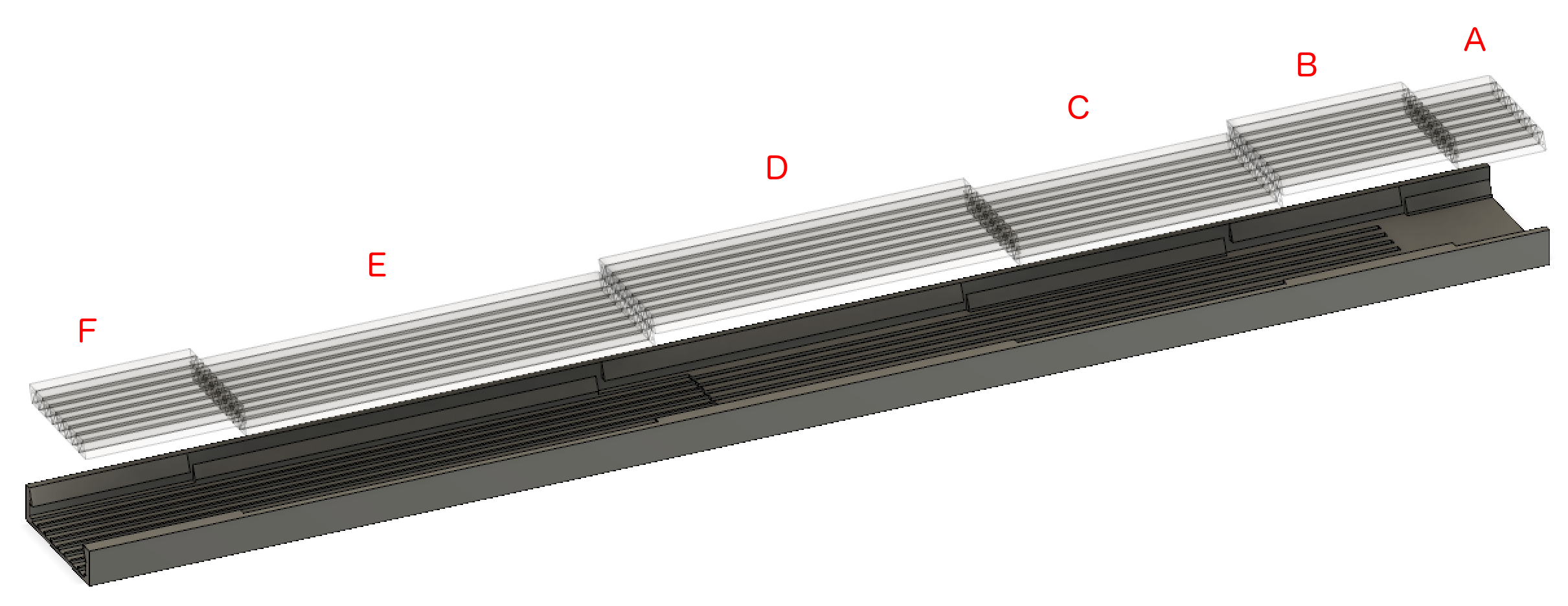
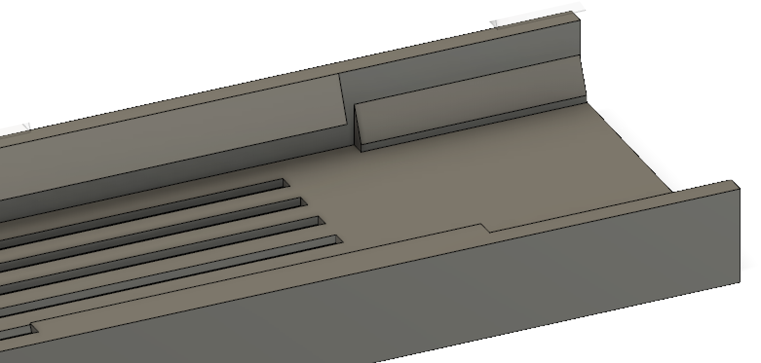
| The tray is 50 cm long, but the printer has a 9" bed,
so I cut the tray into 3 sections. The little platforms support the B,D,F
bars.
tray/tray1.stl tray/tray2.stl tray/tray3.stl tray/bridge1.stl tray/bridge2.stl tray/bridge3.stl
Look at these files here: viewstl.com
| 
| |||||
| (34) We add cooling tubes in order to be able to cool the SiPMs. Details here. Jan 2019 | 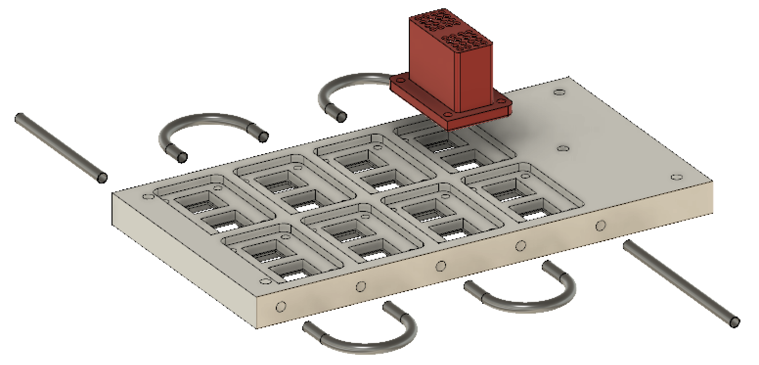
| |||||
| (33) A board is being developed to hold 16 4x4 SiPMs. Details here. | 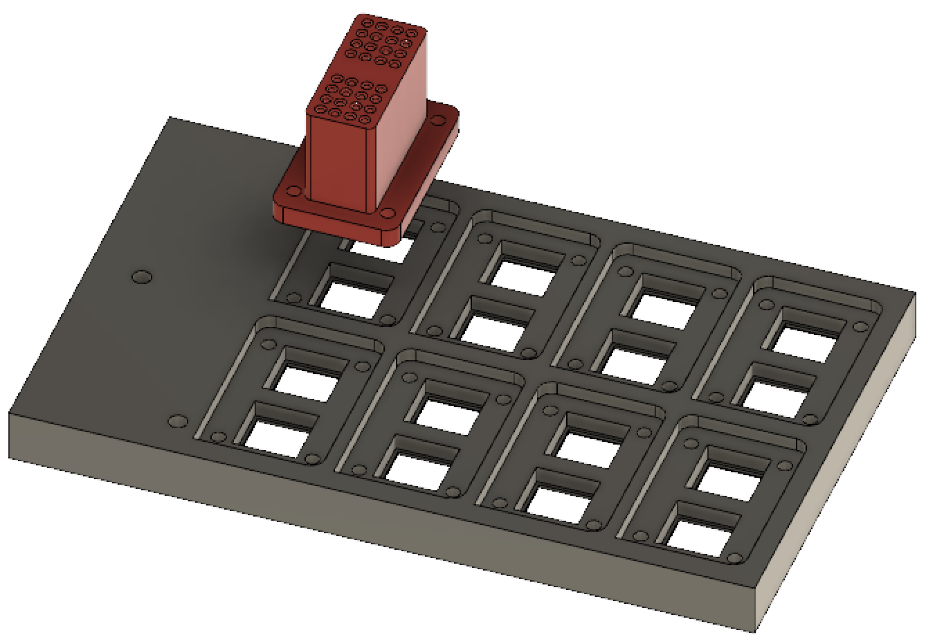
| |||||
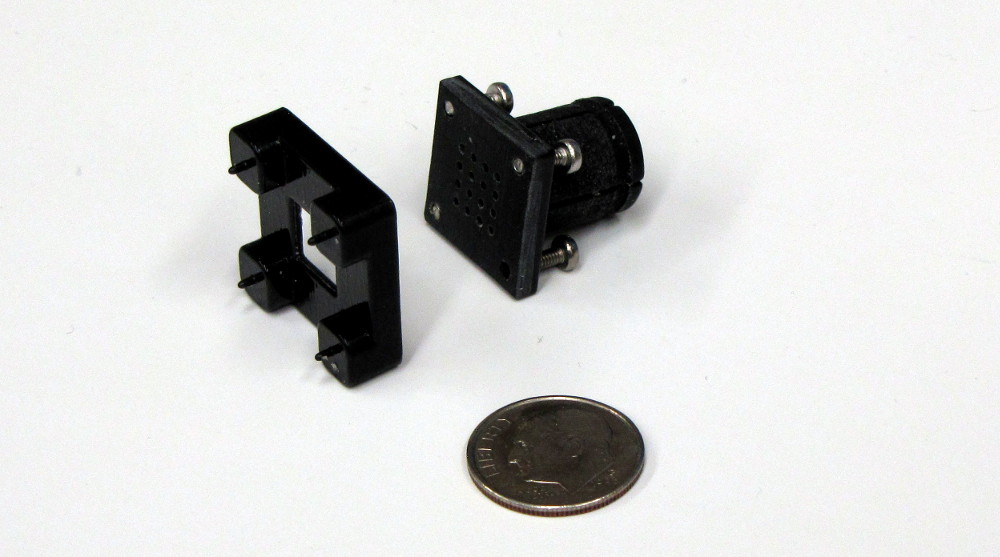
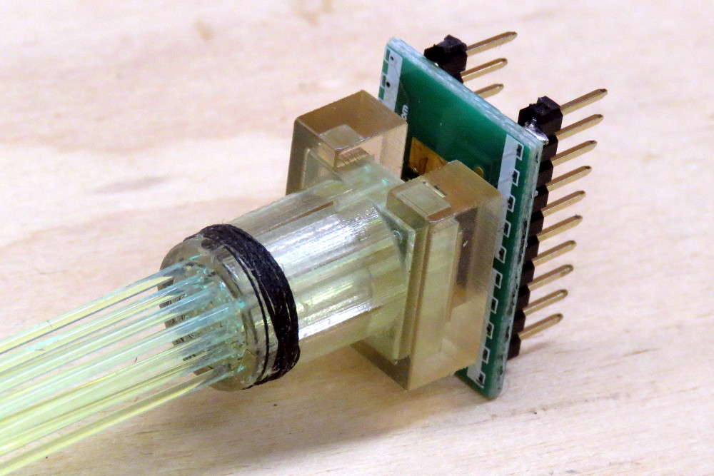
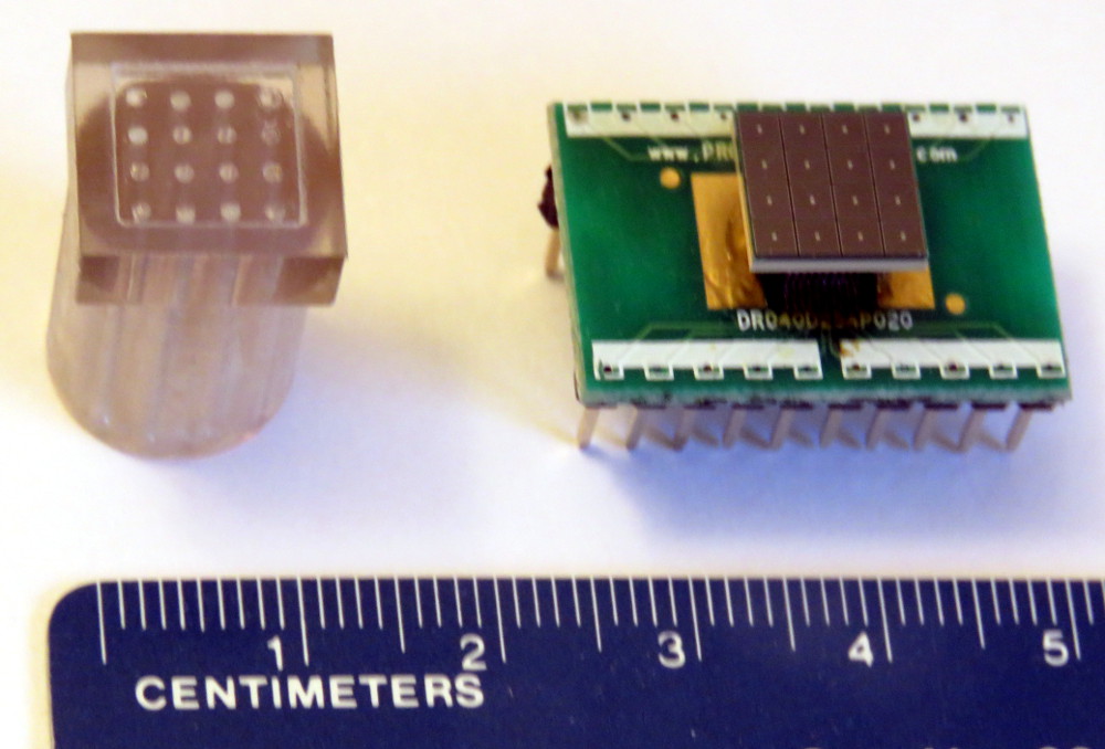
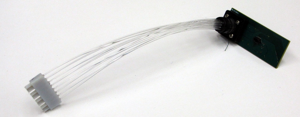
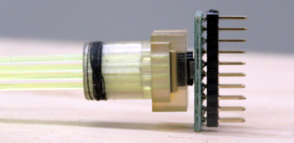
| (32) The assembly, where clear fibers from a 16-fiber coupler go to the 4×4 holder, which is mated with the SiPM holder and mounted on a PC daughter board. The base measures 22×22 mm.
| 
| |||||
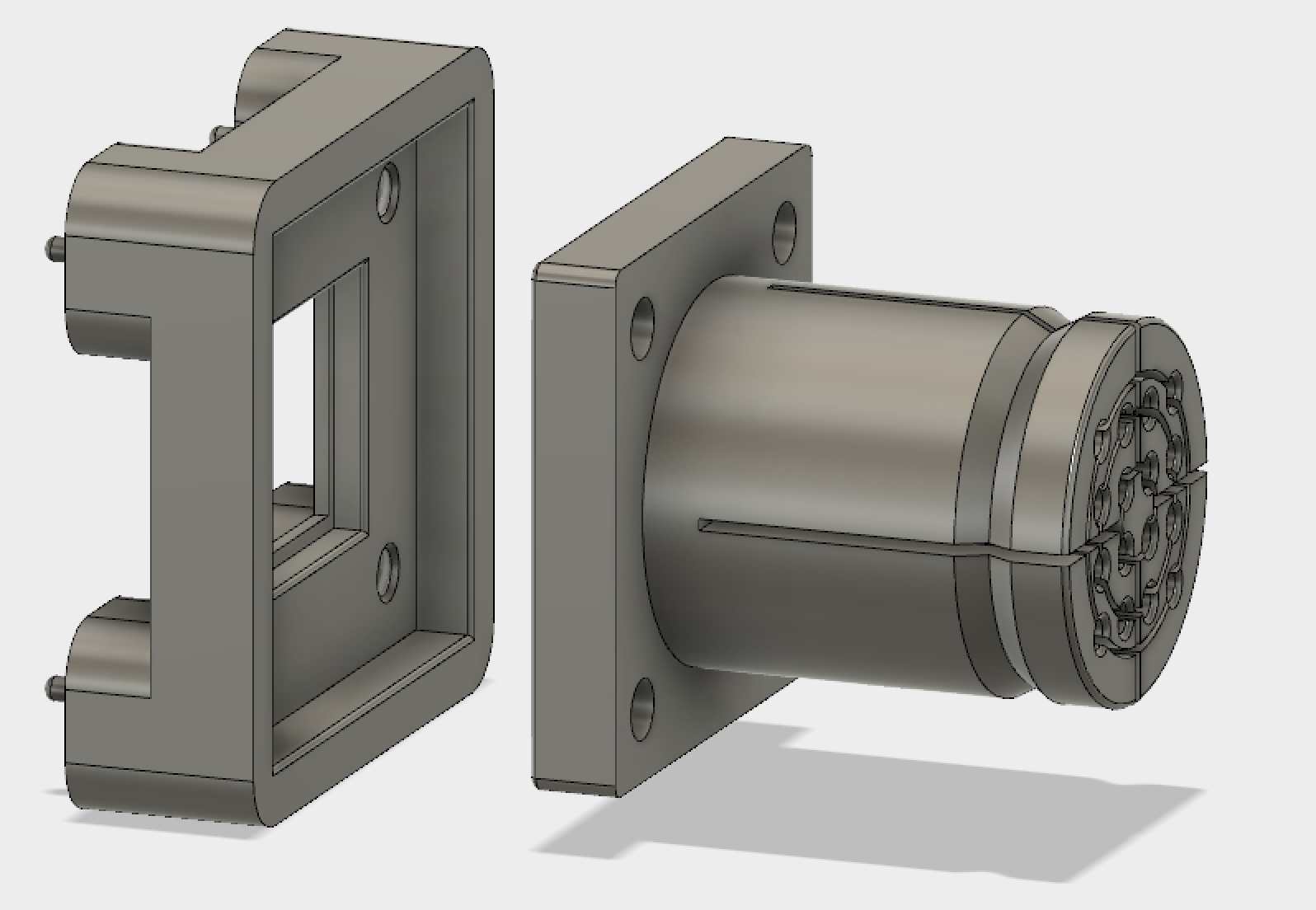
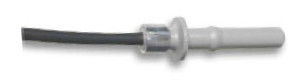
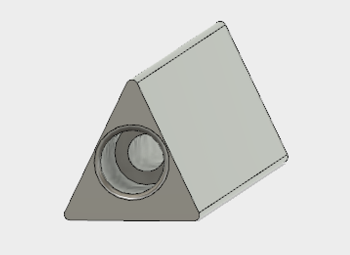
| (31) This is the SiPM base, plus the fiber holder. The base fits into the 4 holes in the PC board (these pins are 0.85mm diam.). On the front of the base is a well for the SIPM, and 4 M2 screw holes. |
| |||||
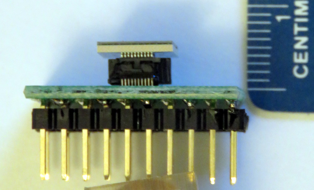
| (30)
SiPM board connector
The bottom of the SiPM sits on the top of the connector (red arrow). The
specs place this at 3.50mm from the surface, but the measured height of the
4 connectors, at both corners is 3.45, 3.46 (3x), 3.48 (2x), 3.49 (2x).
So I will place the SiPM bottom at 3.50mm high.
Note the large tolerance on the sensor thickness, 1.35±0.20 mm. | 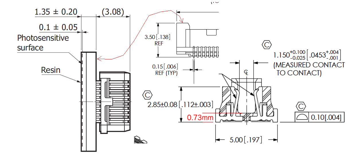
| |||||
| (29)
| 
| |||||
| (28) Slide the scintillators onto the fibers
| 
| |||||
| (27) After sanding and polishing in 4 steps, the fibers are flush with the end of the conector | 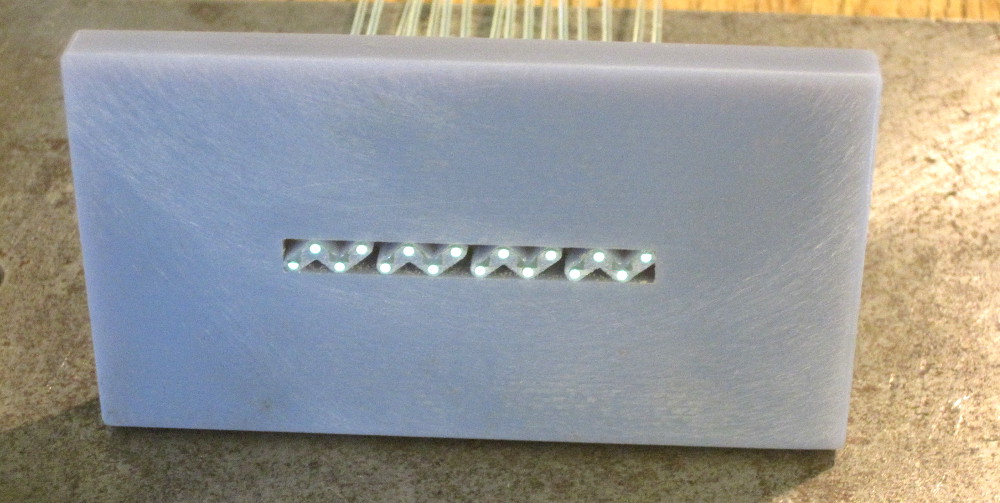
| |||||
| (26) Glue the fibers into the connector, making them protrude about 0.5mm. Use the sanding block, and spacers cut out of paper and cardboard. | 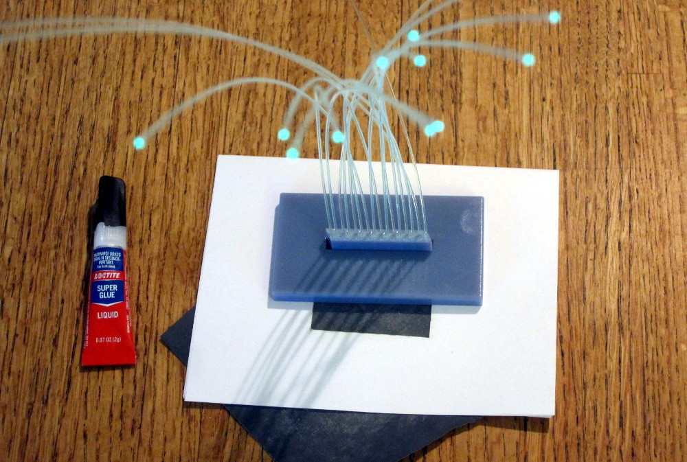
| |||||
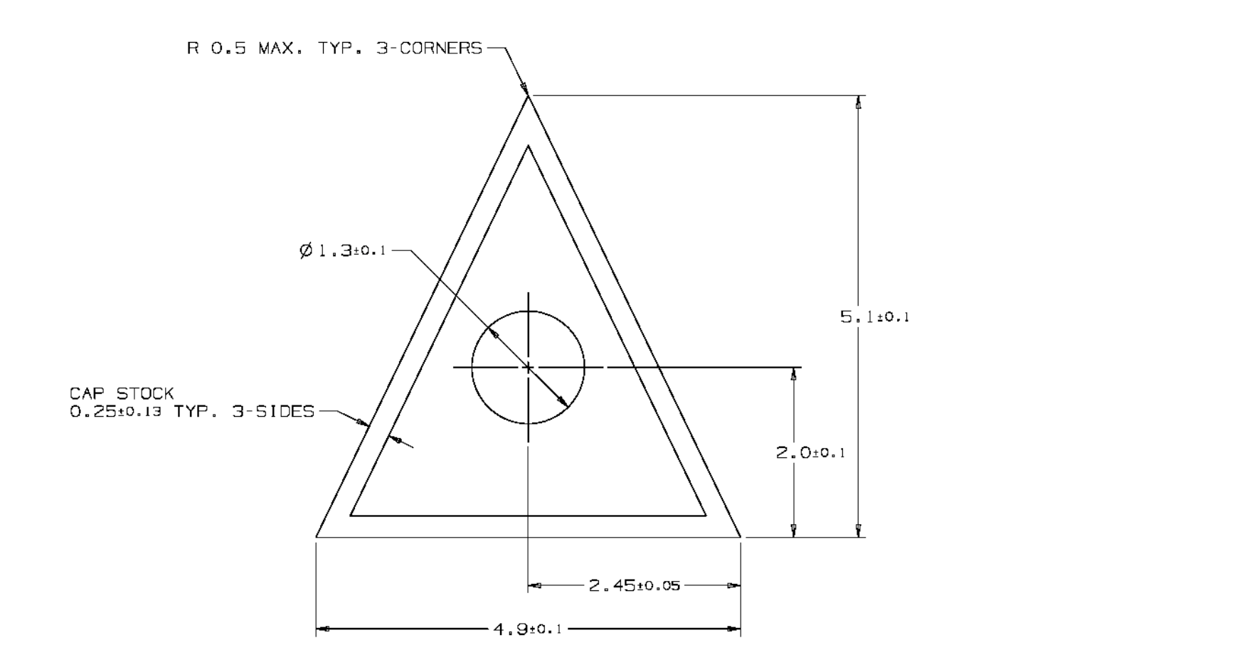
| (25) Cut all scintillators to length with a Dremel tool | 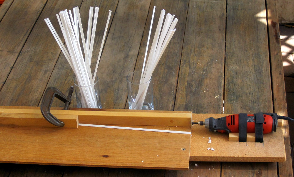
| |||||
| (24) Pictures taken during a visit to the experiment Dec 2018 | 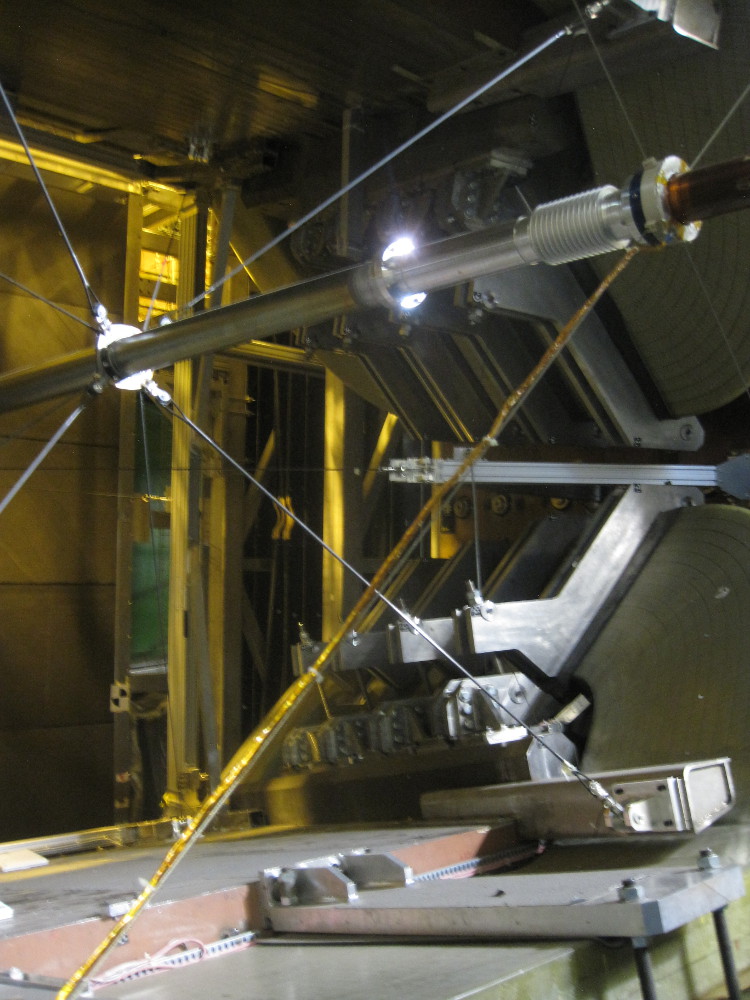
| |||||
| (23) | 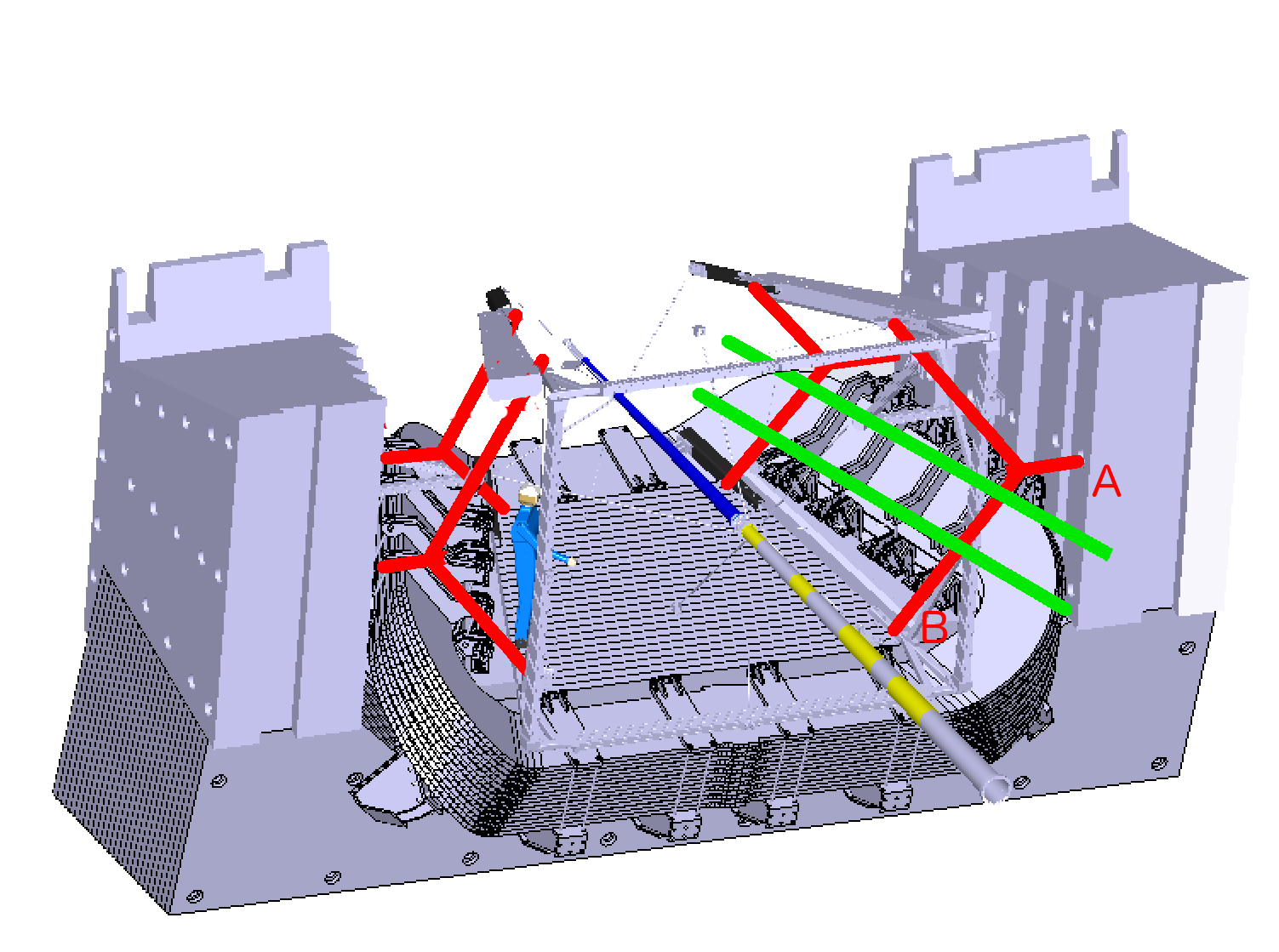
| |||||
| (22) In order to get familiar with the crazy shapes of the LHCb magnet, I built a 1:20 scale model. More here Oct 2017 | 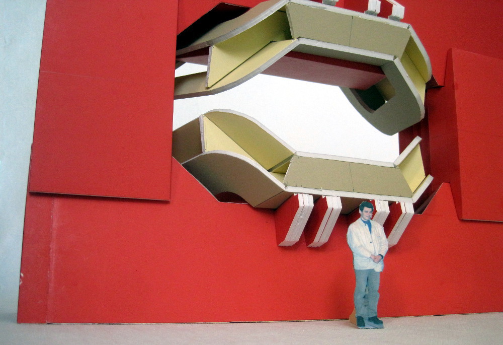
| |||||
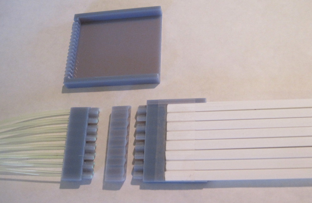
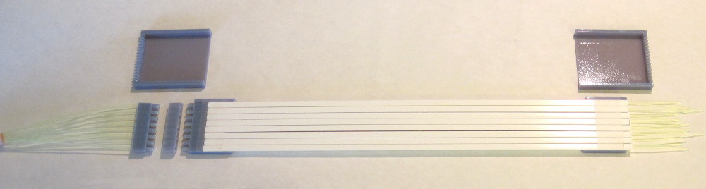
| (21) The scintillator came in, and the holes are lower than originally specified. I redesigned the connectors also: Connectors C and C' are identical (mirror copies). C holds the scintillating fibers, and C' holds the clear fibers. D connects the two. I made gangs of 4, so that the tips are not so vulnerable during the polishing process. | 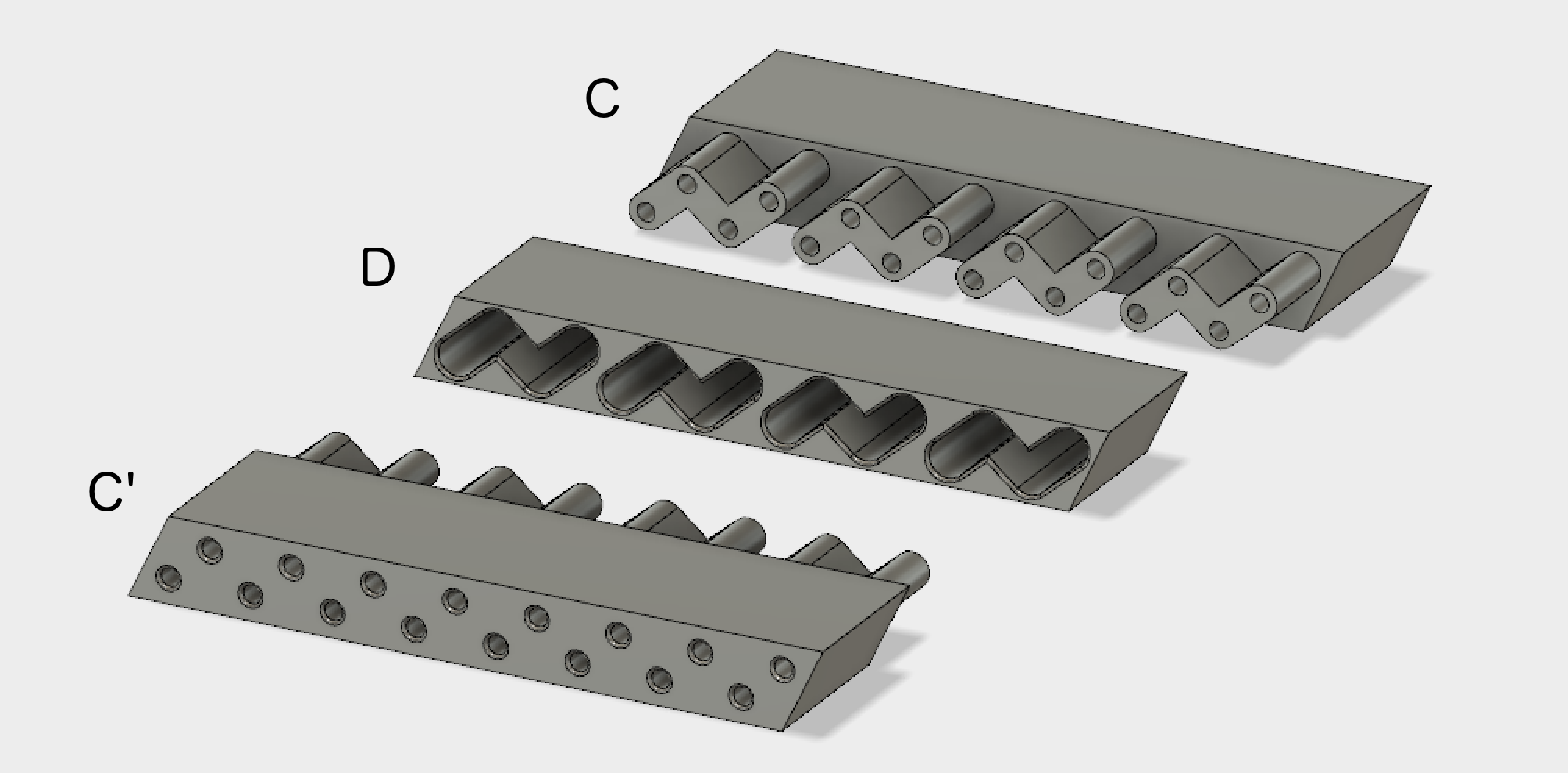
| |||||
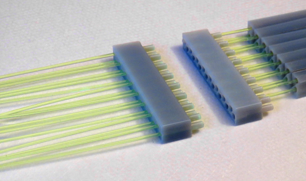
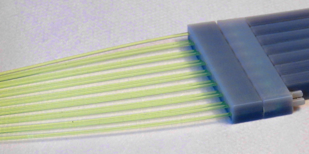
| (20) Here is the printed version: Connector B has (green) fibers inserted (will be clear fibers). Connector A has green fibers inserted, which go into the (temporarily printed) triangular scintillating bars.
In the small picture, the connectors are pushed together. The connectors are
about 4cm wide.
| 
| |||||
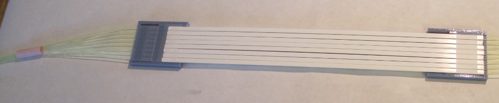
| (19) Connector A holds 16 WLS fibers, and clicks into the scintillator bar
assembly.
Connector B holds 16 clear fibers that go to the 4×4 sensor.
| 
| |||||
| (16) Next step: make a connector that services a block of 16 bars. | 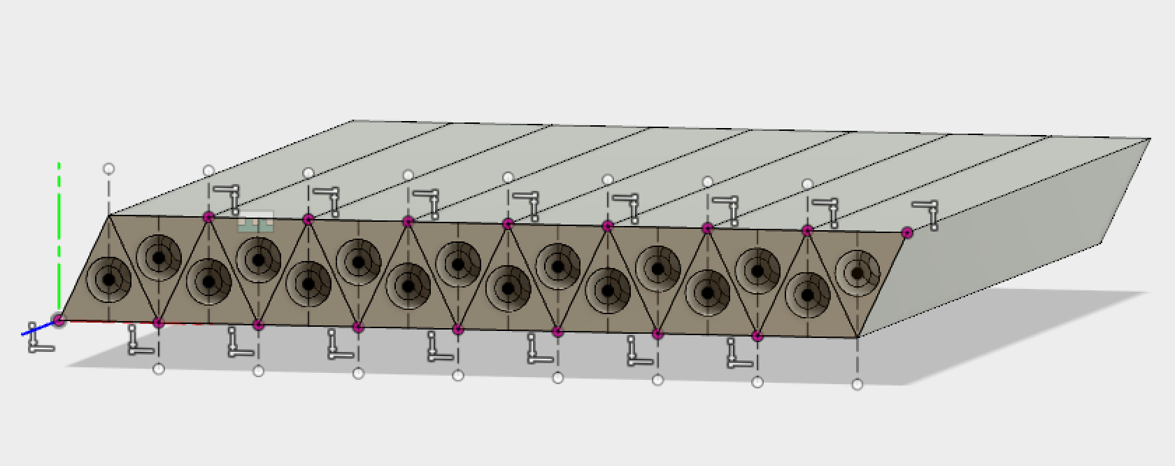
| |||||
| (15) | 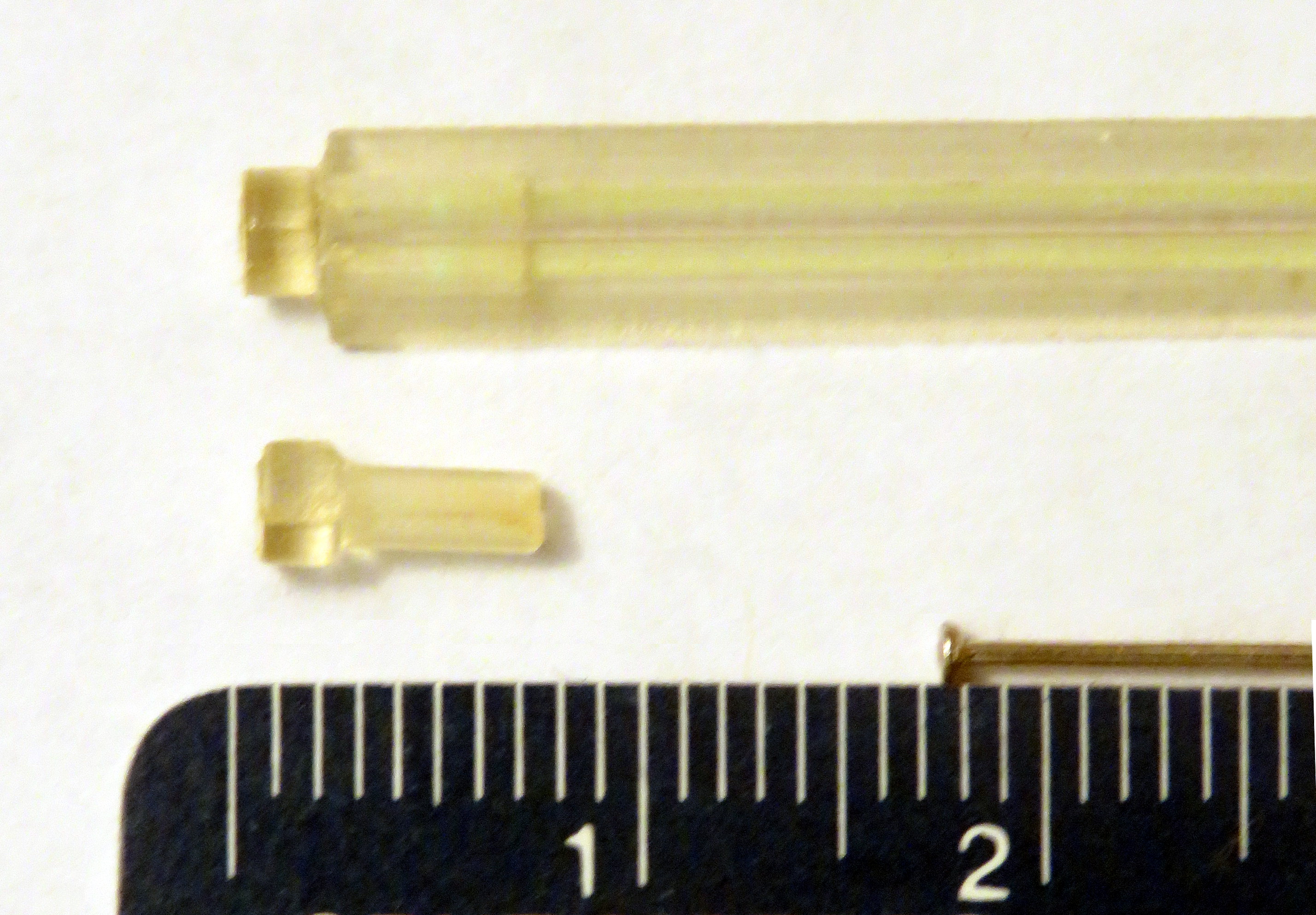
| |||||
| (14) Next round: in the middle are 2 sections of triangular bar. On the right is a coupler, where a clear fiber would come in from the right, and be glued in place about halfway. The wls fiber would slide into the coupler, and slide into the bar. A plug on the left holds the wls fiber, and could also hold a small piece of soft material that keeps the wls fiber pushed to the right, against the coupler with the clear fiber. | 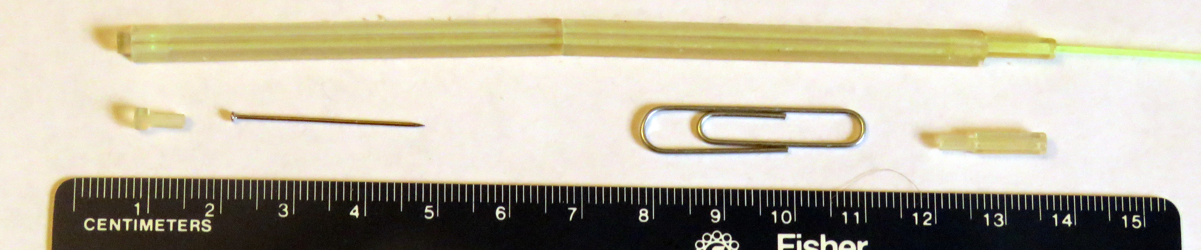
| |||||
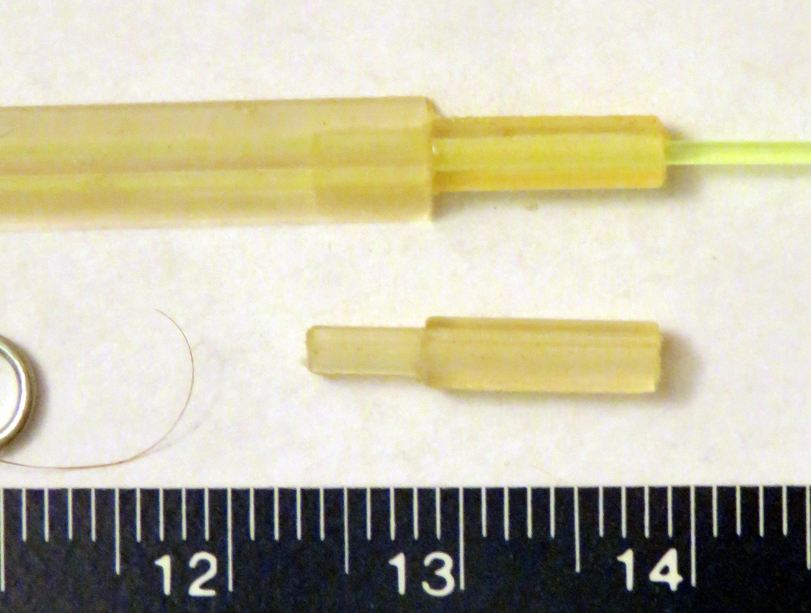
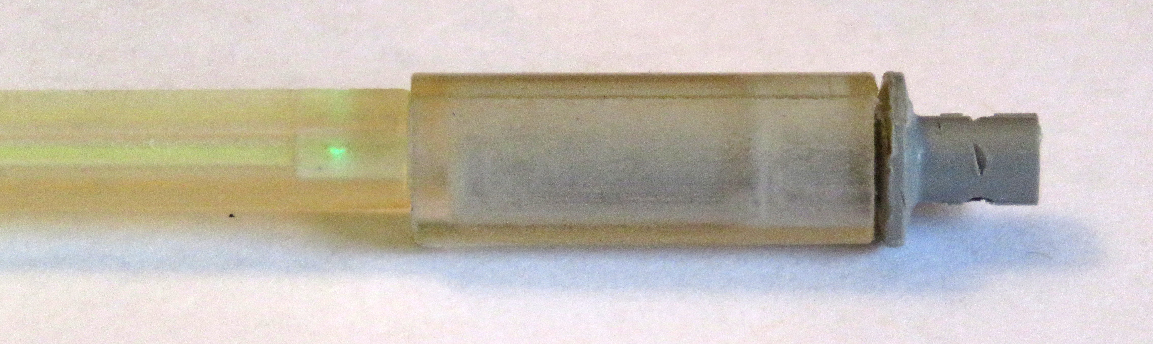
| (13) The 3 pieces connected. A clear 1mm fiber would be in the
commercial coupler. The commercial coupler, and therefore the
intermediate coupler are too large.
| 
| |||||
| (12) A piece of (printed) triangular scintillating bar, a coupler and a commercial 1mm fiber coupler strung onto a 1mm wls fiber. | 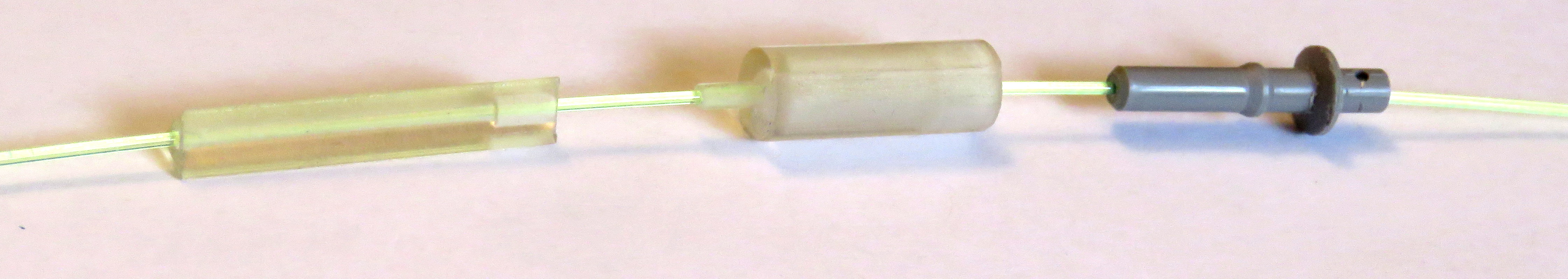
| |||||
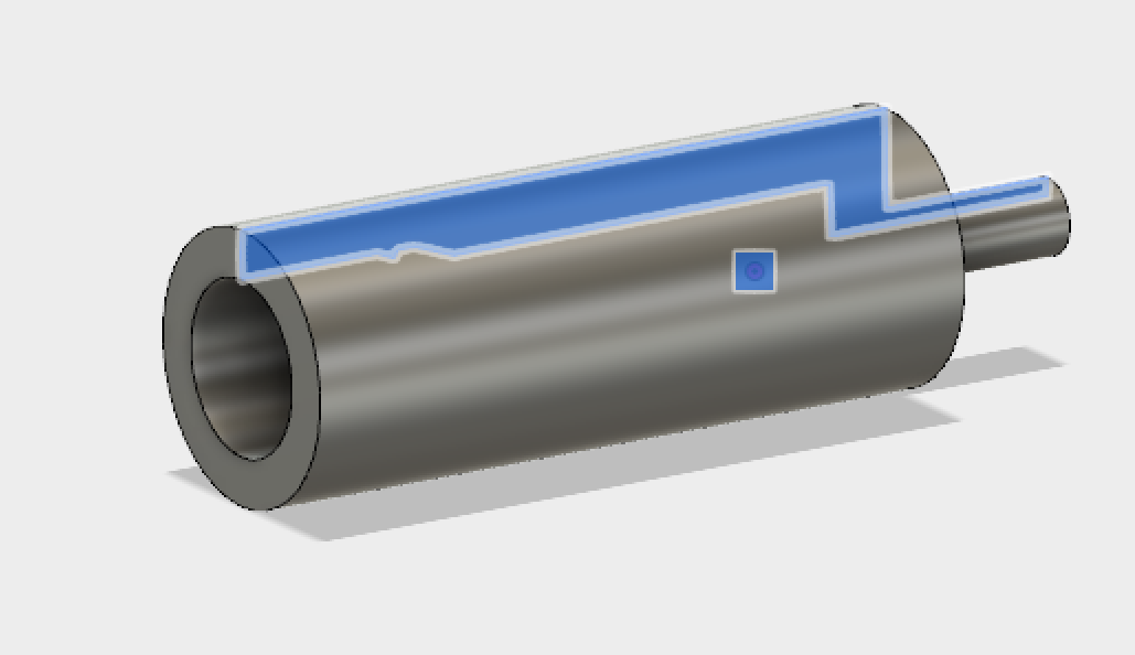
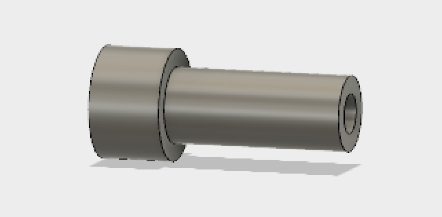
| (11) This is the connector that fits into the bar,
and has an interior profile on the other
side that fits a commercial 1mm fiber connector.
| 
| |||||
| (10) This is the
scintillator bar at the other end of the fiber
| 
| |||||
| (9) Parts assembled
| 
| |||||
| (8) Opposite view | 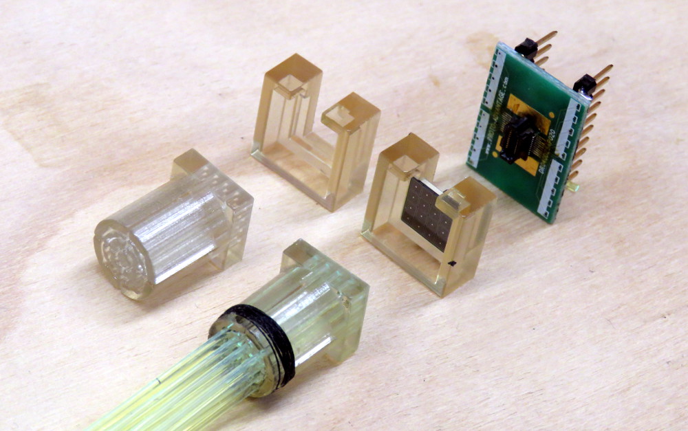
| |||||
| (7) The 16 fibers are cleaved, and inserted into the fiber holder, protruding just a little (~0.5mm). Then they are secured in place by wrapping the back end tightly with (black) thread and wood glue. Next the fibers are sanded flush with the front surface, and polished in stages. The SiPM fits into a 1.5mm deep well. | 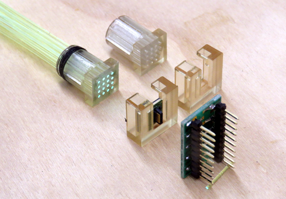
| |||||
| (6) Version 2: the holes are a little bigger, and the slits are a little wider. The front does not have the lip anymore, so that the fibers can be polished in-place, so a clip is needed to position the SiPM. | 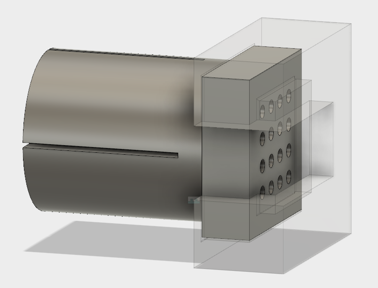
| |||||
| (5) Could not push the fibers all the way through, and there are bridges in the slits, which are therefore not flexible.
| 
| |||||
| (4) Size 25×18 mm. | 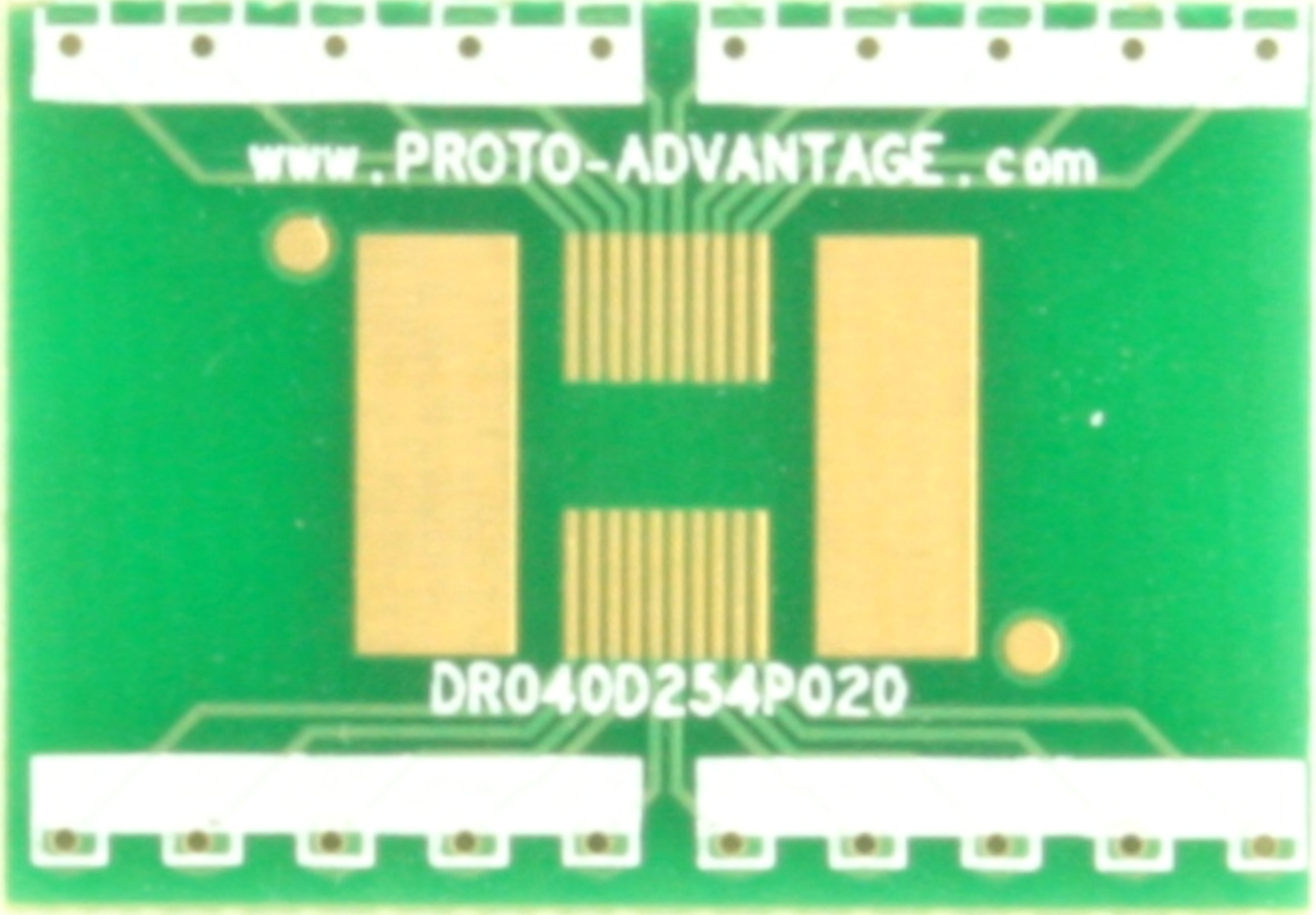
| |||||
| (3) There are slits in the back. A small hose clamp or cable tie around the cylindrical part will cause the fibers to be held tightly. | 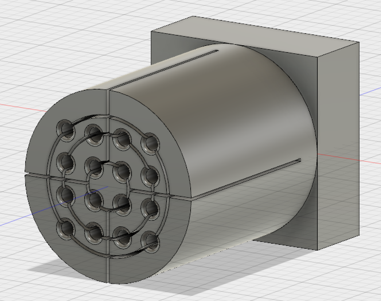
| |||||
| (2) The 9×9 mm SiPM fits into the front. Holes are for 1mm fibers. | 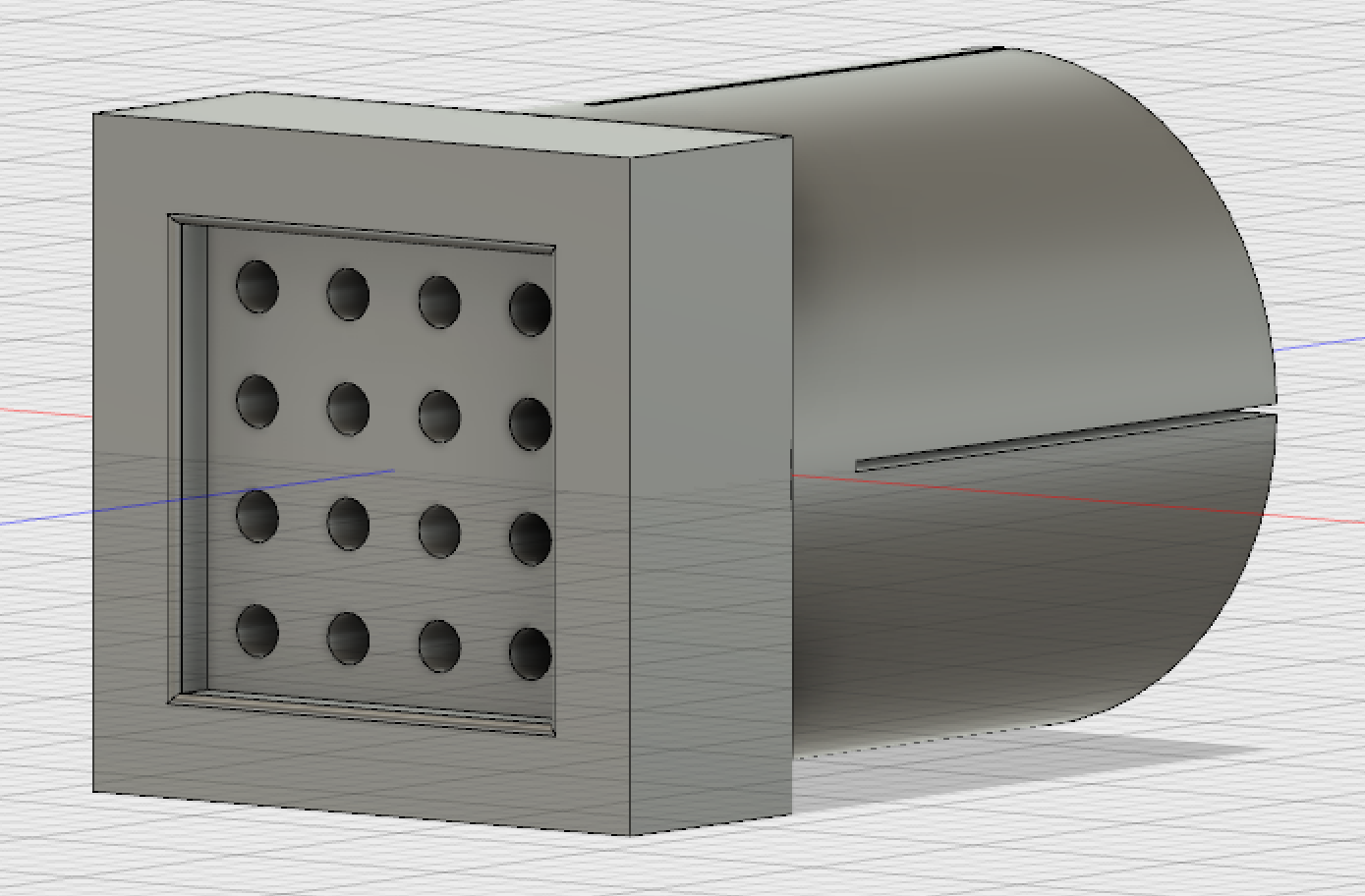
| |||||
| (1) Here is the 4×4 SiPM | 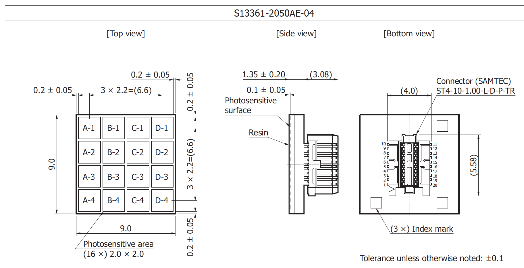
| |||||
back to 'LANL LHCb home'
Hubert van Hecke Last modified: Wed Aug 29 12:08:36 MDT 2018